
A membrane switch is a touch sensitive device created by the printing, cutting and laminating of precision thin film plastic materials. Low-voltage, low-current momentary electrical contact is made and retained by applying finger-tip force to the front surface of the switch.
Membrane switches are primarily utilized with microprocessor based control systems found in medical, communication, instrumentation and appliance products.
Membrane switch technology has become a reliable front panel solution where environmental concerns or frequent cleaning are an issue. The sealed nature of the technology coupled with its reliability and ability to offer tremendous aesthetic flexibility make it the solution of choice for many industries.Types of Membrane Switches:
Non-Tactile Membrane Switches
The most reliable and economical membrane switch is the non-tactile type. However, they do not give the user direct feedback from the switch. Using a LED indicator or display change can sometimes overcome this drawback.
Non-tactile switches also have the advantage of easily creating custom shapes and sizes of the active keypad areas.
 Non-tactile switches also have the advantage of easily creating custom shapes and sizes of the active keypad areas.
Tactile Membrane Switches
Tactile membrane switches have a snap action that is clearly noticeable to the operator. Conductive stainless steel snap domes have the best action. They can also eliminate the need for a flexible upper circuit layer. To ease the final mating of the switch and avoid the possibility of a dome becoming inverted a .015" - .020" backing layer can be provided.
Hydro formed polydomes offer a milder tactile response and a narrower operating temperature range then the metal dome.
Because of the relatively short travel of membrane switches, it is often necessary to provide users with some type of feedback. Feedback can be visual, audible, or tactile. Visual or audible feedback should be a consideration in the electronics design. Domes can be added to a membrane switch to provide tactile feedback. There are two types of domes that we use in membrane switches, stainless steel and polyester. There is no significant difference in reliability between these two dome technologies.
Mixed Panels
Non-tactile and tactile switches can be mixed in the same panel. This can be desirable when a large active area is needed for a particular switch or perhaps hidden maintenance or programming switches.
PCB Backed Membrane Switches
A printed circuit board can be used for the lower circuit. The board can provide structural support and incorporate numerous surface mount components. This assembly can be bonded to your PCB or sub-contractors can be utilized to provide this type of construction.
User Interface
The Graphic Overlay
The appearance of the graphic overlay is integral to the operator's view of the equipment.
Nearly any colors can be produced. The finest line (or space between lines) that can be effectively printed is a .006" thickness. The maximum line screen is 230 LPI (lines per inch) for graduated halftones and process printing.
Embossing can be used with either tactile or non-tactile switches but pillow embossing alone does not give a tactile response.
Display Windows
Integral display windows and LED indicators can be easily incorporated into the membrane switch design.
Single point and block LED's have the least limitations. They will perform well with any of the material surface finishes. However, for greater diffusion a matte or textured surface finish is preferred. LED's cannot come through the active area of a tactile switch, although graphically they can be made to appear as a part of the switch.
Integral (surface mounted) single point LED's can be mounted onto the bottom layer lower circuit. A wide range of colors, including bi-color, are available. Termination can then be provided from the same connector tail as the switches, if the graphic layer is embossed to accommodate the LED's. The graphic does not need to be embossed if the LED termination is provided on a separate tail.
Digital windows can be designed to enhance the specific display that will be used. Texture will distort the appearance of displays that are not directly against the overlays. Matte and gloss finishes work best. Translucent filtering inks can be printed to improve a displays appearance.
For an LCD the window will remain uncolored. The matte (anti-glare) finish offers more scratch resistance than the gloss (clear) finish but may diffuse displays further then .060" away.
A red LED displays appearance will be improved with the addition of either a RED or SMOKE GRAY color. Use red to achieve better readability in low light conditions or smoke gray when used in brighter conditions or with other colored LED's.
The concept is the same for use with Green or Yellow (amber) LED's. Use GREEN or AMBER yellow filters, respectfully, for low light conditions or smoke gray in brighter conditions.
DEADFRONTING (hidden until lit) is an additional option that can be included if the legends are against a dark background.
Selective Texturing
Selective texturing is a screen-printed application of a scratch resistant surface hardcoat to the front face of the graphic overlay. The purpose is to improve the clarity of display windows or to visually emphasize specific areas.
A textured hardcoat can be applied to glossy or anti-glare material. This results in the best display windows. Another method is to apply a clear hardcoat to textured material.
Material Selection
A variety of overlay materials are used in membrane switch applications.
Polycarbonate is a commonly used material because it is easy to print on, die cut and emboss – making it a very cost effective alternative. The disadvantage of polycarbonate is that it begins to show signs of wear sooner than some of the alternate materials. In most applications polycarbonate overlays will last a minimum of 100,000 cycles during life cycle testing. Uncoated polycarbonate is also susceptible to damage from a variety of chemicals. If a polycarbonate overlay is going to be in an environment that will subject it to chemicals, a hardcoat should be used to protect the overlay.
Polyester is a more robust material that has superior life cycle and chemical resistance properties. In life cycle testing, polyester shows no signs of wear at 1,000,000 cycles. However, polyester, due to its memory properties, frequently requires hydroforming rather than embossing. Hydroforming is more expensive for both tooling and unit cost. Polyester is also more difficult to die cut resulting in more frequent reblading of steel rule dies.
Both polyester and polycarbonate are available with a variety of textures and hardcoats. In their uncoated glossy form both materials are very susceptible to scratching. For this reason we recommend that gloss materials receive a hardcoat.
Equipment Interface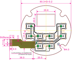
Circuit Design - Configuration
Tracking lay-out can affect the reliability and ease with which the membrane switch can be manufactured. Therefore, the pin-out (i.e. the order in which the tracks exit the tail) should be left to the switch manufacturer when possible. The best pin-out can then be provided by the manufacturer to you as part of the design preparation process.
Switches can be connected using:
1.A common line configuration (A common bus, ground, connects a number of different switches. This works well with a smaller number of switches and is generally an easier layout to engineer).
2.A matrix configuration (An X-Y matrix for interconnecting columns and rows is created. This greatly reduces the number of tracks relative to the number of switches that the connector will require).
3.A mixture of the two.
Shielding
The graphic overlay materials have a relatively high dielectric strength and high volume resistivity. A higher degree of electrical shielding, when necessary, can also be incorporated into the construction of a membrane switch. The requirements can vary significantly depending upon the intended industry the product is designed for.
Shields can be designed for the following:
ESD (Electrostatic Discharge)
EMI (Electromagnetic Interface)
RFI (Radio Frequency Interface)
Conductive inks or metalized (aluminum clad) polyester can be used to introduce an additional shield to the switch beneath the graphic layer.
Grounding can be accomplished with a separate tail or using the same connector as the circuitry. Alternatively a grounding tab can be created for connecting to a metal backing plate or support panel.
Venting
A pocket of air exists between the contacts of the switch. This air must be displaced when the overlay is depressed. Normally venting tracks to accommodate this displacement are designed between switches a part of the spacer layer by the switch manufacturer. This will result in a completely sealed switch and is perfect under normal atmospheric conditions.
Pin outs
The schematic or pin out of a switch may be specified by the customer if necessary; however, as with any circuit layout, the more freedom we are allowed the more efficient layout we can produce. This has the advantage of shorter development time and a simpler circuit layout, which could affect switch cost. Membrane switches can be designed with a common bus or in a matrix. Matrix layouts are desirable for keyboards with many keys to simplify the interconnect.
Connector Tail
The position of the tail should be carefully planned as it could have substantial impact on the design of the membrane switch. A minimum clearance of .10 from tail edges for the tracks and a .040 minimum for each track must be allowed.
The tail is formed from the circuit layers. Therefore, no feature requiring a circuit track (i.e. switch or integrated LED) can be between the tail exit point and the edge of the panel.
The easiest exit location that can be produced is to bring the tail straight out of a panel edge (edge exit). This works fine if a bezel will cover the panel edge. Also easily accomplished is if the tail can exit just inside the panel's perimeter.
If the tail must exit from within the perimeter (inset exit) then a tail filler must be used to replace the missing circuit layers. Alternatively a WATER TIGHT NEMA 4 type perimeter seal can be utilized at an additional cost when necessary.
A male or female connector can be fitted to the end of the tail.
Exposed silver should be covered with carbon to avoid silver migration and not be adversely affected by moisture.
Integrated LED's
Surface mount single point LED's can be integrated into a membrane switch circuit. However they cannot be mounted within the active switch area. Bi-Color LEDs can also be utilized.
Electrical Performance
The large variety of membrane switch designs can make it difficult to outline a general set of specifications that covers all membrane switches.
Listed below are some basic performance specifications.
Loop Resistance: The loop resistance of a switch is a function of trace width and length. In most applications the maximum loop resistance is less than 100 Ohms.
Open Circuit Resistance: 50 Mega Ohms minimum
Contact Rating: 100 Milli-amps at 28 VDC Maximum
Maximum Load: 1.5 VA Nominal
Contact Bounce: 5 Milliseconds Nominal
Operating Temperature: -20°C to +75°C
Cut-outs & Parameters
Switch cut-outs (unless a bezel covers the opening) should be .030" overall larger than chassis openings. Allow at least .062" between cut-outs and active switch or window areas.
Normally the membrane overlay is made slightly larger than the layers beneath and recesses should be .010" larger all around to assure a proper fit.
Care should be taken that graphics are not obstructed with any bezels fitting around cut-outs.
Laser Cutting
The various layers of a membrane switch can be cut out by using a numerically controlled laser. This technology offers two advantages. Tighter mechanical tolerances can be held, and no tooling is required. While laser cutting is a more expensive process than die cutting, in many low and medium volume applications it is quite cost effective.
Voice of the Customer
This form can be used as an aid in putting together your blueprint. The information noted will help us in manufacturing a part that meets all of your requirements.
You will find:
You will find:
General Requirements: any special quality requirements that you have related to FMEAs, PPAP’s, regulatory requirements, etc.
Faceplate Requirements: all of the details required for the top layer that carries all of the colors and defines the key nomenclature.
Electrical Requirements: all of the details required for the switch itself.
Tolerances: printing, die cutting, and assembly tolerances are noted.
Sample Blueprint
This blueprint shows an example part with all of the details noted for the switch and faceplate to give you an idea of what a typical finished blueprint would look like.
Please contact us today with you requirements.